

Laser Shearography Inspection is a cutting-edge Non-Destructive Testing (NDT) technique, offering unmatched capabilities in detecting subsurface defects such as disbonds, delaminations, and voids across a wide range of materials and structures.
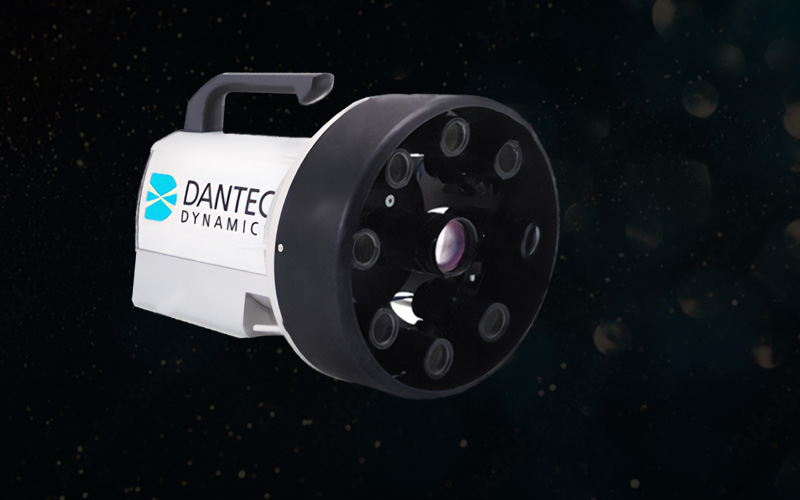
Laser Shearography
By utilizing laser interferometry, Laser Shearography observes out-of-plane deformation responses when materials are subjected to stress. With its origins in aerospace manufacturing and now expanded to industries like automotive, civil engineering, and marine, this method ensures the integrity and safety of critical components and structures.
Laser Shearography – Overview
NDT and Evaluation with LS
The process involves applying a load—whether thermal, vacuum, mechanical, or acoustic—to a material. Surfaces with hidden defects deform differently than sound areas, revealing discontinuities. A monochromatic laser illuminates the material’s surface, generating a speckle pattern. By analyzing shifts in the speckle pattern through image subtraction, Laser Shearography creates a shearogram (visual map) of the strain field, where fringe patterns highlight subsurface anomalies. This technique is highly sensitive, detecting deformations as small as 30 nm, and allows for rapid inspection with minimal preparation.
Unique Benefits:
- High-Speed Inspection: Capable of inspecting large areas quickly, significantly outpacing traditional methods.
- Versatility: Effective on a variety of materials and geometries, including complex shapes.
- Sensitivity: Detects microscopic changes, making it ideal for identifying minute defects.
- Operational Simplicity: Requires minimal setup and preparation, making it suitable for both lab and field inspections.
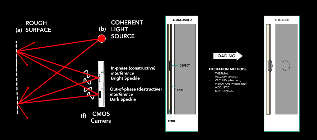
An Infographic on Laser Shearography
(a) Rough Surface
The rough surface represents the object or component being inspected for defects using Laser Shearography. It is typically a composite structure or bonded material that could contain flaws such as disbonds, delaminations, or cracks. The roughness of the surface scatters the coherent light (from the laser source), creating a speckle pattern that is analyzed for changes in response to applied loading or excitation. The purpose of inspecting the rough surface is to detect local weaknesses or defects that cause changes in the surface deformation under stress.
(b) Coherent Light Source
A “coherent light source” refers to a laser used in the shearography system. Coherent light means that the emitted photons are in phase and have the same frequency, resulting in a consistent and predictable wave pattern. This property is crucial in generating interference patterns (speckle patterns) when the light is reflected off a rough surface. The laser is used to illuminate the surface, and the reflected light creates a speckle pattern that forms the basis of the interferometry analysis. The phase differences in this light, when the material is loaded, allow for the detection of defects.
(f) CMOS Camera
The CMOS camera is an integral part of the Laser Shearography system, capturing the speckle patterns generated by the interference of reflected laser light. The CMOS (Complementary Metal-Oxide-Semiconductor) sensor is used for its high sensitivity and speed, which are critical in capturing the changes in the speckle pattern before and after loading (or excitation) of the surface. These changes are analyzed to create a phase map that indicates areas of local deformation, which helps identify defects.
In-Phase Constructive Interference (Bright Speckle)
In-phase constructive interference occurs when two or more light waves reflected from the surface remain in sync, meaning their peaks and troughs coincide. This leads to an increase in amplitude, creating bright spots or “bright speckles.” In shearography, constructive interference is used to enhance areas of the surface that experience minimal deformation, allowing these areas to appear bright. Bright speckles suggest that there are no significant stress concentrations or defects, as the material’s response is consistent and predictable.
Out-of-Phase Destructive Interference (Dark Speckle)
Out-of-phase destructive interference occurs when the peaks of one wave align with the troughs of another, canceling each other out and reducing the overall amplitude. This results in dark spots or “dark speckles.” In Laser Shearography, dark speckles are important as they often correspond to areas of significant deformation or changes in material properties, indicating possible defects. The contrast between bright and dark speckles allows for a visual indication of stress concentrations and potential discontinuities in the material.
Finding the Defect in the Loaded State
Once an excitation method is applied to the surface (such as thermal, vacuum, vibration, acoustic, or mechanical loading), the object being tested is deformed slightly. The CMOS camera captures the speckle patterns before and after this deformation. The difference between these two states is displayed as a phase map with fringe patterns.
In the “loaded” state, the defects are indicated by irregularities or disruptions in the fringe patterns. When a defect is present, the local stiffness of the material changes, causing non-uniform deformation. These local areas of discontinuity manifest as isolated or irregular fringe lines, indicating a defect like a crack, disbond, or delamination. The operator interprets these fringe anomalies to locate and assess the severity of the defect.
Excitation Methods
An “excitation method” refers to the type of loading or stress applied to the surface being inspected in order to induce slight deformations.
These methods can include:
- Thermal Loading: Heating the material to cause thermal expansion, which reveals differences in thermal response due to defects.
- Vacuum (Partial or Ambient): Applying a vacuum creates a pressure differential that slightly deforms the surface.
- Vibration (Mechanical): Applying mechanical vibration to the surface to induce dynamic deformation, which can highlight discontinuities.
- Acoustic Loading: Using acoustic waves to create pressure variations that stress the surface.
- Mechanical Loading: Directly applying mechanical force to the material to induce bending or stretching.
These excitation methods help make defects more visible by causing differential deformation at the defect site compared to the surrounding defect-free material. By comparing the speckle patterns before and after excitation, the presence and location of flaws are determined.
Applications and Advantages
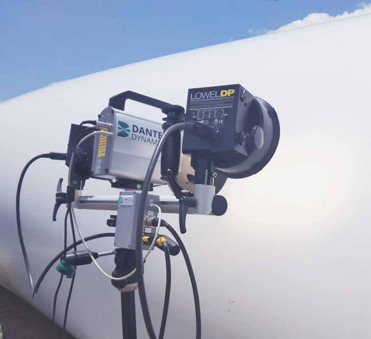
Originally developed for the United States Air Force to inspect the B-2 stealth bomber, Laser Shearography has since evolved into a versatile tool, applicable across various industries. It is particularly effective for inspecting composite materials, which are often challenging for traditional NDT methods. Laser Shearography can inspect large aerospace fuselages, microcircuits, and even masonry cracks in historic buildings, all with impressive speed and accuracy.
A Global Collaboration in Advanced NDT with Laser Shearography
CICNDT, in a global collaboration with Dantec Dynamics, is advancing non-destructive testing (NDT) by integrating Dantec’s state-of-the-art Laser Shearography systems with CICNDT’s extensive expertise in field applications. This partnership leverages Dantec’s advanced NDT technology and CICNDT’s proven track record in handling complex inspection environments to offer unmatched inspection capabilities across multiple industries.
The Laser Shearography system, known for its ability to detect subtle surface deformations caused by subsurface defects, provides high-resolution, real-time results. The technology excels at inspecting large, complex structures and is particularly effective in identifying defects like disbonds, delaminations, and voids in composite materials.
This collaboration not only brings together cutting-edge technology but also combines the specialized expertise of both organizations. Together, CICNDT and Dantec enable industries to perform high-precision testing with increased reliability, ensuring the integrity of critical components in sectors like aerospace, wind energy, and marine.
Key Benefits of the Global Collaboration:
– Comprehensive Expertise: Merges Dantec’s leading Laser Shearography technology with CICNDT’s extensive field experience, particularly in challenging environments where accuracy and speed are essential.
– Robust and Portable Systems: The Laser Shearography equipment is designed to be rugged and portable, providing consistent performance in both controlled and harsh field conditions.
– Precision and Efficiency: Provides detailed defect analysis and high-speed inspection rates, ensuring that even the most demanding inspection requirements are met with efficiency and accuracy.
– Advanced Applications: This collaboration empowers clients by offering turnkey solutions and the ability to integrate Dantec’s Laser Shearography systems into their in-house quality assurance programs, elevating their NDT capabilities.
Through this global collaboration, CICNDT and Dantec Dynamics deliver industry-leading NDT solutions, ensuring the safety and reliability of critical components while enabling clients to harness cutting-edge Laser Shearography technology for their operational needs.